Stand-alone lwIP Echo Server
These reference designs can be used with the stand-alone lwIP echo server application template that is
part of Vitis; however, some modifications are required. The lwIP library needs some modifications to be able to
properly configure the Marvell PHYs (88E1510) that are on the Ethernet FMC. The Vitis directory of the
source repository contains a script that can be used to setup a Vitis workspace containing the echo server
application and the modified lwIP library.
The build script does the following:
Creates a Vitis workspace in the
Vitisdirectory of the source repository.Creates a subdirectory called
embeddedswto be used as a local software repository containing the modified lwIP library.Copies the sources from the
EmbeddedSwdirectory of the repository to the local software repository (embeddedsw), then copies any remaining/unmodified sources from the Vitis installation directory into the local software repository.Generates a lwIP Echo Server example application for each exported Vivado design that is found in the
Vivadodirectory. Most users will only have one exported Vivado design.
Building the Vitis workspace
To build the Vitis workspace and example application, you must first generate the Vivado project hardware design (the bitstream) and export the hardware. Once the bitstream is generated and exported, then you can build the Vitis workspace using the provided scripts. Follow the build instructions — the steps are the same on Windows and Linux.
Run the application
You must have followed the build instructions before you can run the application.
Launch the Xilinx Vitis GUI.
When asked to select the workspace path, select the
Vitis/<target>_workspacedirectory.Power up your hardware platform and ensure that the JTAG is connected properly.
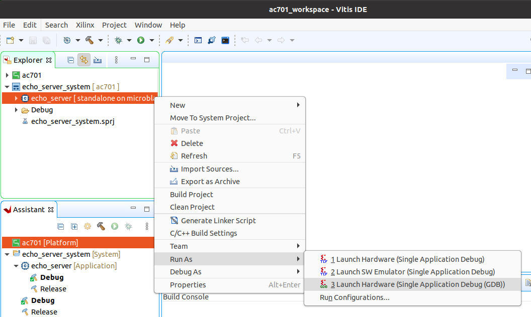
In the Vitis Explorer panel, double-click on the System project that you want to run - this will reveal the application contained in the project. The System project will have the postfix “_system”.
Now right click on the application “echo_server” then navigate the drop down menu to Run As->Launch on Hardware (Single Application Debug (GDB))..
The run configuration will first program the FPGA with the bitstream, then load and run the
application. You can view the UART output of the application in a console window and it should
appear as follows (captured from a pz_7030 boot — ZynqMP targets prepend a
Zynq MP First Stage Boot Loader banner):
-----lwIP TCP echo server ------
TCP packets sent to port 6001 will be echoed back
Start PHY autonegotiation
Waiting for PHY to complete autonegotiation.
autonegotiation complete
auto-negotiated link speed: 1000
Board IP: 192.168.2.72
Netmask : 255.255.255.0
Gateway : 192.168.2.1
TCP echo server started @ port 7
The above output results when the target port is connected to a router with DHCP. The assigned board IP can vary. If DHCP fails the echo server falls back to a static IP — see IP address below.
UART settings
To receive the UART output of this standalone application, you will need to connect the USB-UART of the development board to your PC and run a console program such as Putty. The following UART settings must be used:
Microblaze designs: 9600 baud
Zynq and ZynqMP designs: 115200 baud
IP address
By default, the echo server attempts to obtain an IP address from a DHCP server. This is useful if the echo server is connected to a network. Once the IP address is obtained, it is printed out in the UART console output.
If instead the echo server is connected directly to a PC, the DHCP attempt will fail and the echo server’s IP address will default to 192.168.1.10. To be able to communicate with the echo server from the PC, the PC should be configured with a fixed IP address on the same subnet, for example: 192.168.1.20.
Change the target port
The echo server example design currently can only target one Ethernet port at a time.
Selection of the Ethernet port can be changed by modifying the ETHERNET_PORT define
in the platform_config.h.in file located in the workspace application sources
(eg. <target>_workspace/echo_server/src/platform_config.h.in).
Set ETHERNET_PORT to one of the following values:
0: Ethernet FMC Port 01: Ethernet FMC Port 12: Ethernet FMC Port 23: Ethernet FMC Port 3
Example usage
Ping the port
The echo server can be “pinged” from a connected PC, or if connected to a network, from
another device on the network. The UART console output will tell you what the IP address of the
echo server is. To ping the echo server, use the ping command from a command console of a PC
that is connected to the echo server (either directly or via network).
Example command: ping 192.168.1.10
Connect with telnet
We can also connect to the echo server using telnet and confirm that it is sending back (echoing) the data that we are sending it. From the command prompt of a PC on the same network as the echo server, run the following command:
Example command: telnet 192.168.1.10 7
The first argument of the telnet command specifies the IP address of the device to connect to (in our case the echo server). The last argument in the command specifies the port number, which should be 7 for the echo server.
In the blank screen that opens after running the command, you can type letters and they will be sent to the echo server and be echoed back.